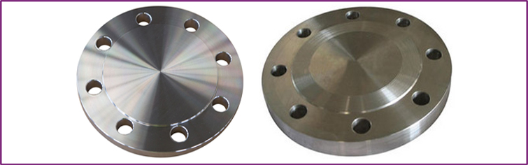
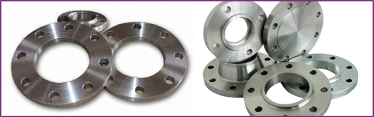
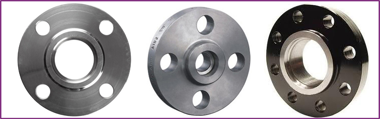
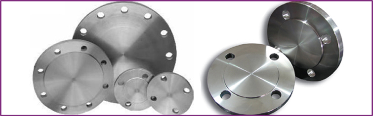
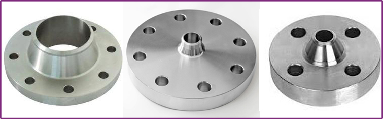
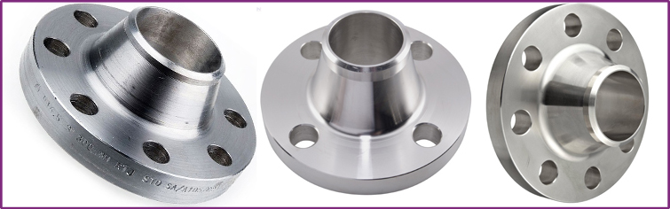
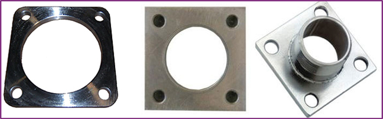
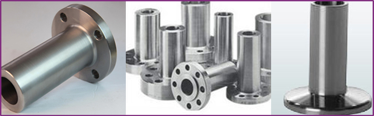
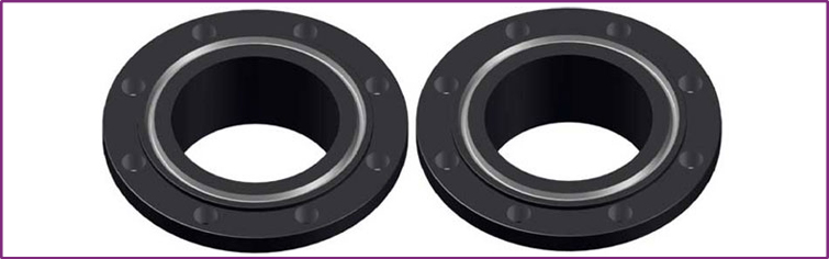
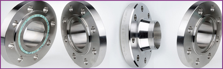
The Blind Flange is used to close ends of piping systems. It is a kind of round plate with no center hold but with all the proper bolt holes. This blind flange is available in various sizes and materials and is used to provide positive closer on the ends of pipes, valves or equipment nozzles. This flange helps in easy access to a line once it has been sealed. The blind flange is sometimes custom made or machined to accept a nominal sized pipe to which reduction is being made. This reduction can be a threaded reduction or welded reduction.
Blind Flanges Product Range
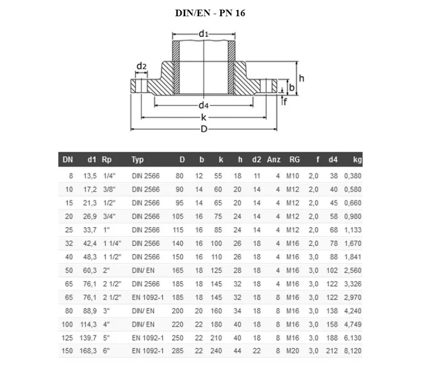
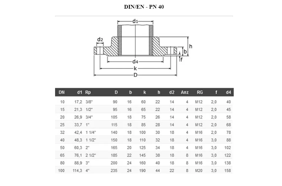
Range : ½” (15 NB) to 48″ (1200NB) in 150 LBS, 300 LBS, 600 LBS, 900 LBS, 1500 LBS, 2500 LBS ASA 150, ASA 300, PN 6,10,16,25, 40,64,100,160 ETC. Available with NACE MR 01-75
Stainless Steel Blind Flanges
Grade : 304, 304L, 304H, 309, 310, 310S, 316, 316Ti, 316 L, 317, 317L, 321, 347, 347 H, 409, 410, 410S, 420, 430L
Duplex Steel Blind Flanges
Grade : 2205 (UNS No. S31803), 2507 (UNS No. S32750)
Nickel Alloy Blind Flanges
Grade : Nickel 200 (UNS No. N02200), Nickel 201 (UNS No. N02201), Monel 400 (UNS No. N04400), Monel 500 (UNS No. N05500), Inconel 800 (UNS No. N08800), Inconel 825 (UNS No. N08825), Inconel 600 (UNS No. N06600), Inconel 625 (UNS No. N06625), Inconel 601 (UNS No. N06601), Hastelloy C 276 (UNS No. N10276), Alloy 20 (UNS No. N08020), Titanium (Grade I & II)
Copper Alloy Blind Flanges
Grade : UNS No. C 10100, 10200, 10300, 10800, 12000, 12200, 70600, 71500, UNS No. C 70600 (Cu -Ni- 90/10), C 71500 (Cu -Ni- 70/30)
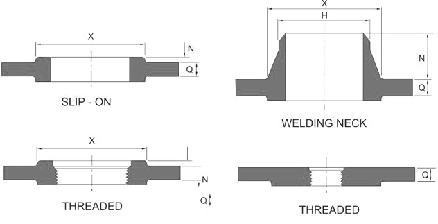
Variations:
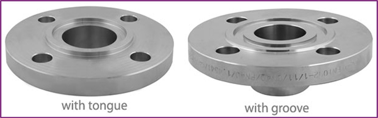
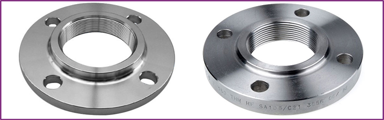
Face finish : Raised face (RF) – Flat face (FF) – RTJ – …
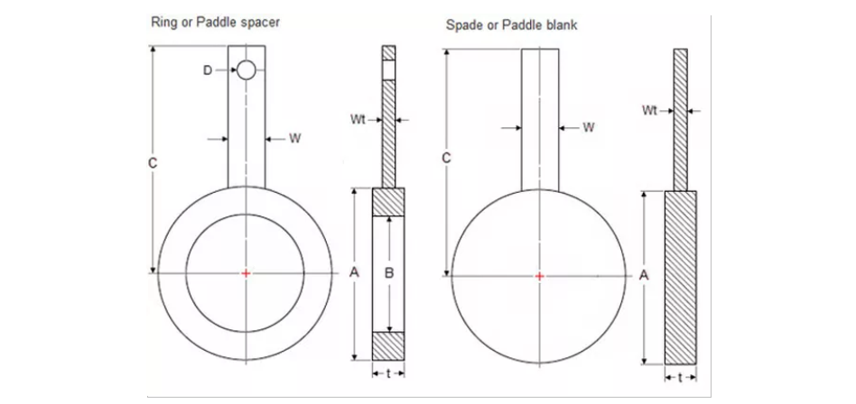
Variations : Spectacle Blind
Standards:
ASTM A182 – ASME SA182 – ‘Standard Specification for Wrought Austenitic Stainless Steel Piping Fittings’
ASME B16.5 – ‘Pipe Flanges and Flanged Fittings’
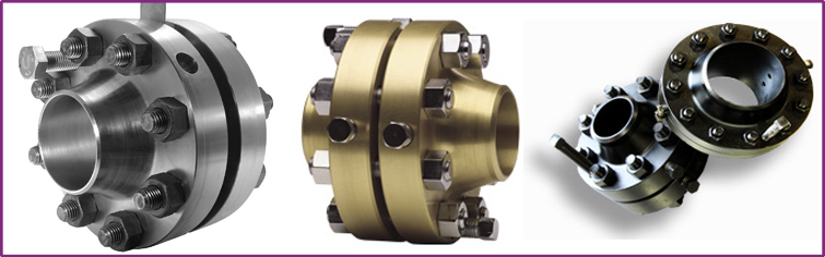
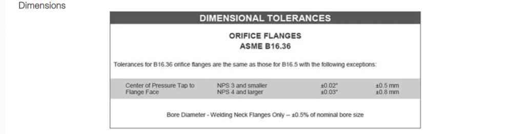
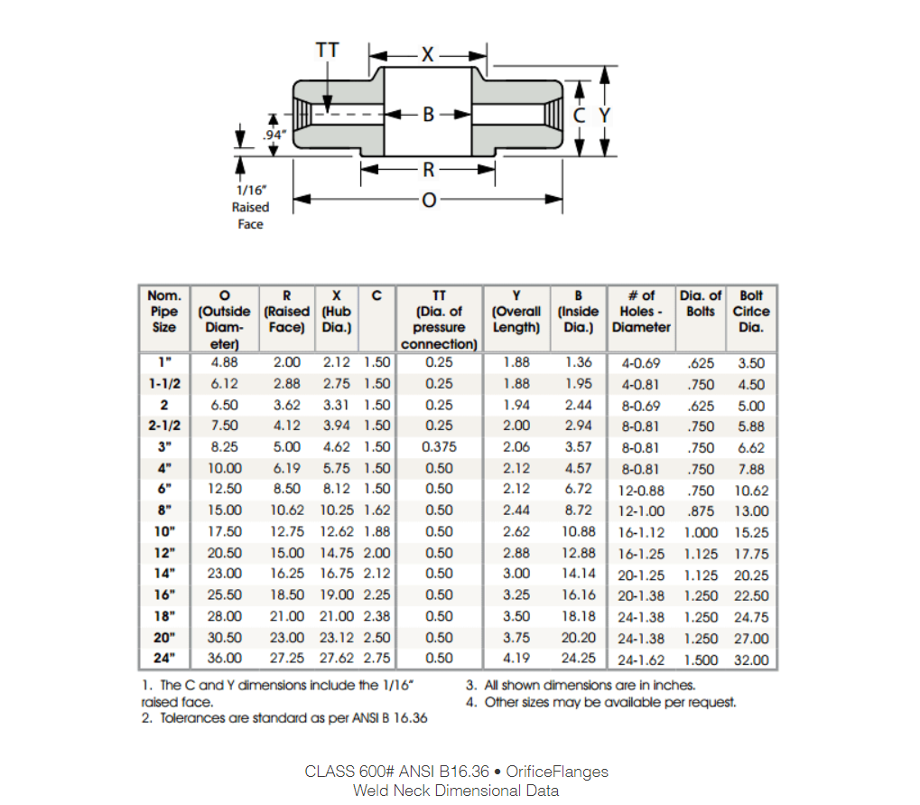
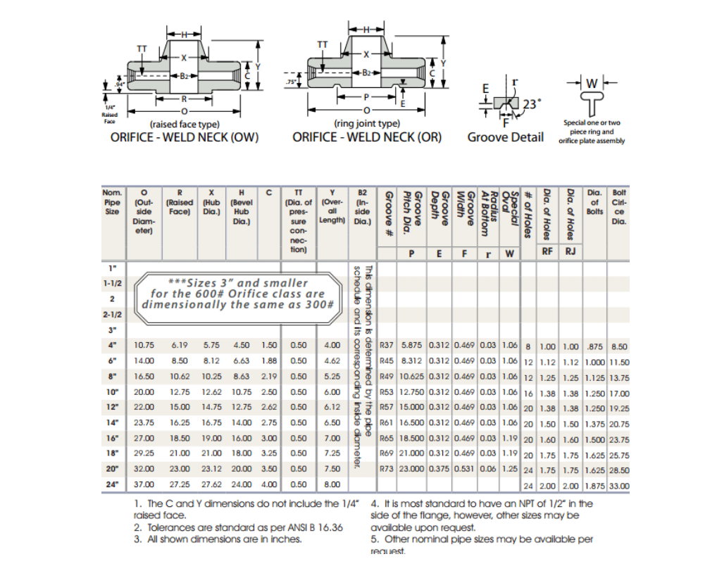
ASME B16.36 – ‘Orifice Flanges’
ASME B16.47 – ‘Large Diameter Steel Flanges NPS26 Through NPS60’
MSS SP-6 – ‘Standard Finishes for Contact Faces of Pipe Flanges and Connecting End Flanges of Valves and Fittings’
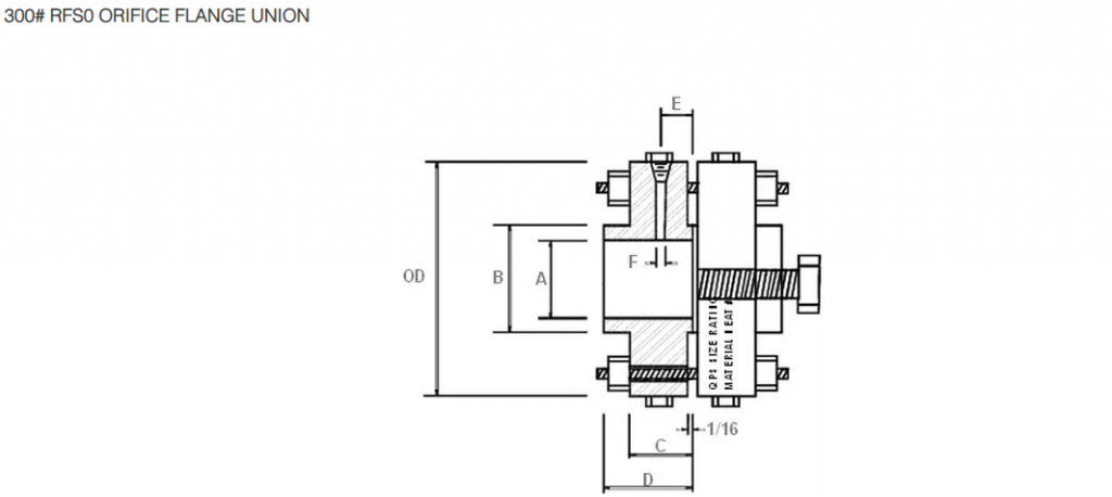
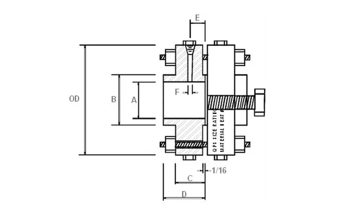
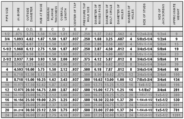
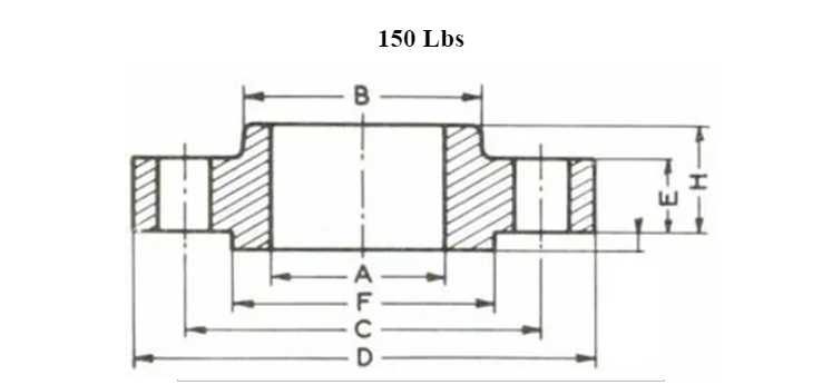
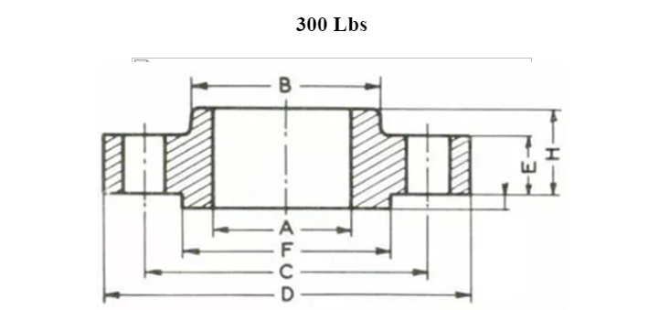
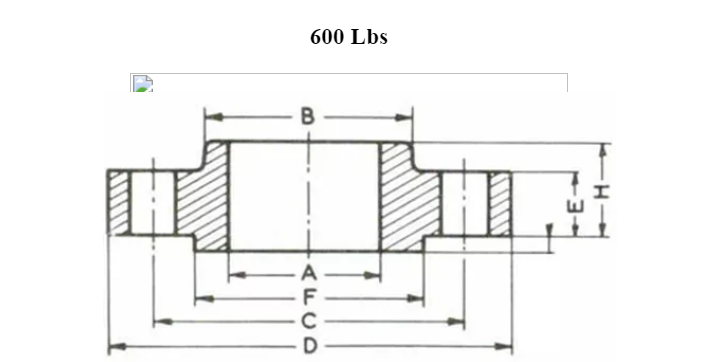
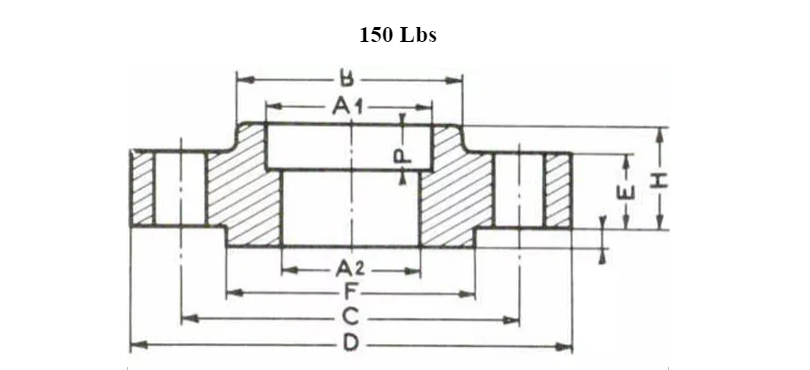
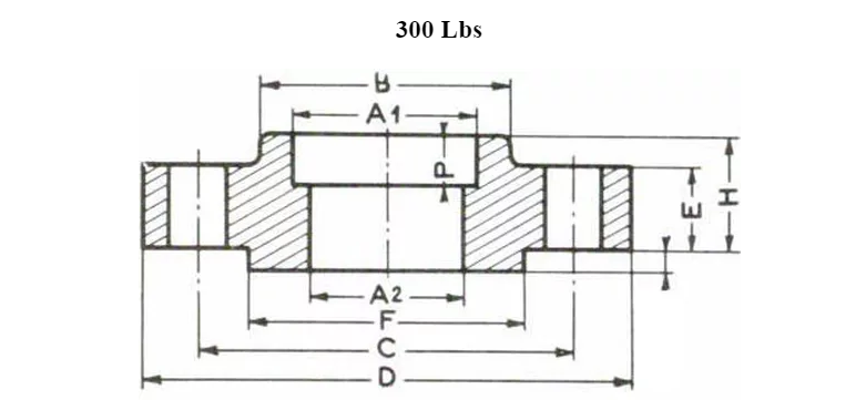
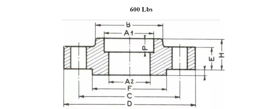
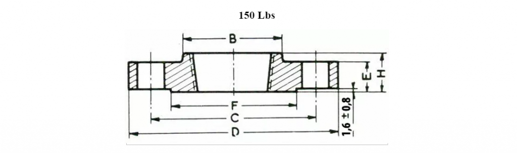
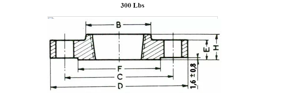
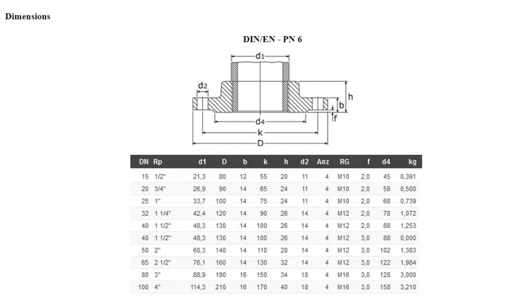
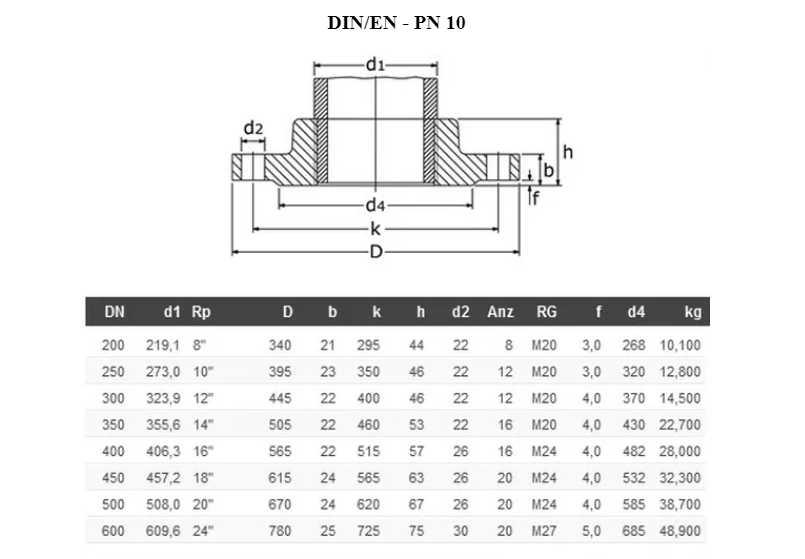
Dimensions
Diameter : 1/2″ à 24″
Pressure class : 150# – 300# – 600# – 1500#
Grades : F304, 304L, 304H, 316, 316L, 316Ti, 310, 310S, 321, 321H, 317, 347, 347H,904L Duplex stainless steel UNS S31803, 2205, Super Duplex stainless steel UNS S32750
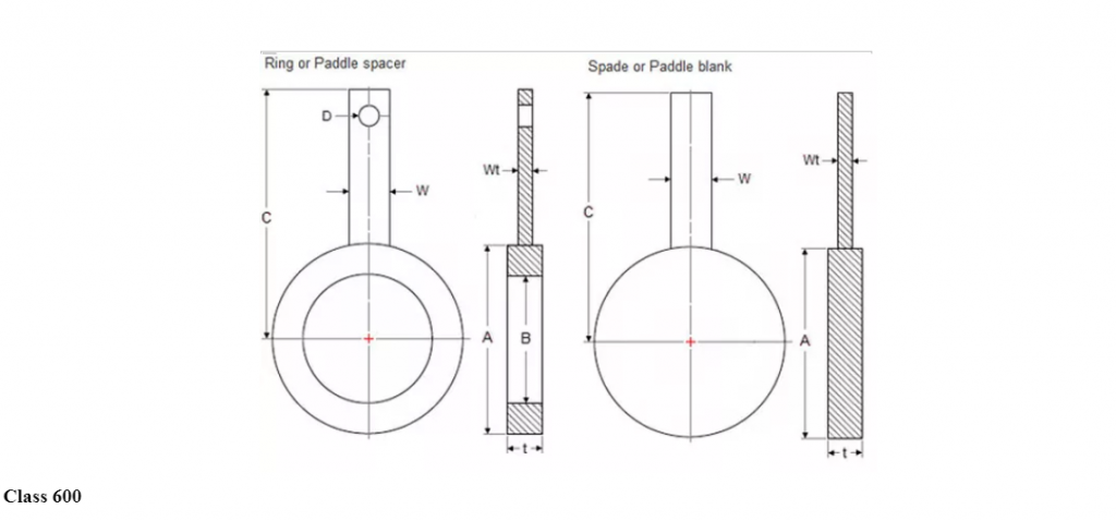
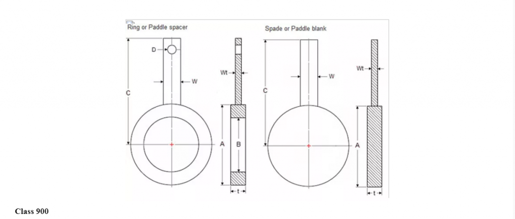
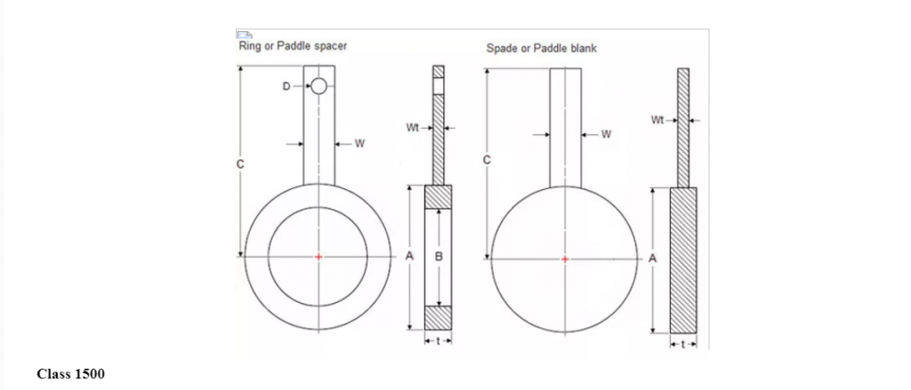
Class: Class 150, Class 300, Class 400, Class 600, Class 900, Class 1500
Features of blind flanges:
Some important features of blind flanges are as follows:
Blind flanges are sometimes supplied with NPT fittings which allow pressure test connections to be fitted.
They are used to blank off the ends of pipe.
They are also used to blank off the ends of valves and pressure vessel opening.
Considering factors like internal pressure and bolt loading, blind flanges, especially in the larger sizes, are the most highly stressed of all types of flanges.
Since the maximum stresses in a blind flange are bending stresses at the center, they can safely be allowed to be higher than in other types of flanges
Blind flanges are made to fit standard pipes in all sizes..
Notes :
Flange dimensions to ANSI to B16.5.
Dimensions “D” includes raised face thickness.
Larger outlet sizes available on applications.
ANSI 150# / 300# 2mm Raised Face.
ANSI 600# / 2500# 7mm Raised Face.